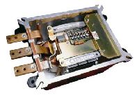
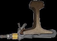
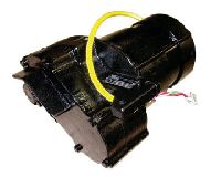
The Train Stop is used in conjunction with wayside signals in rapid transit systems to ensure observance of, and compliance with, restrictive indications. Failure to comply with the rules reqarding such indications results in activation of the train's braking system. Operation is completely automatic, entirely independent of any action on the part of the motorman. The system functions by mechanical contact between a wayside trip arm and a trip cock lever on the underside of the train. The wayside trip arm is lowered when the signal is clear and is raised when the signal is at "stop" or "danger". In the raised position, the trip arm will engage the trip cock lever of any train attempting to pass the signal, thus bringing it to a stop. The Train Stop mechanism, housed in a cast-iron case, consists of a combined motor and gear housing, circuit controller with driving arm, compression return spring and sector gear. The general arrangement of these components is shown to the left. The machine by itself measures 9-78" high by 21-1316" wide by 26-38" long and weighs approximately 250 pounds. Shown in Figure 2 below is a plan view of the Train Stop installed in a typical layout. It is mounted on two ties and includes the mechanism case. The trip arm assembly is mounted on the rocker shaft. One end of the rocker shaft is attached to the output shaft of the Train Stop mechanism. The other end is supported by an adjustable bearing strap. A trip hook assembly is mounted on top of the bearing strap and is used to hook or hold down the trip arm when required. Figure 3 on the following page shows a side view of the trip arm in the tripping position. The trip arm is driven under electric power to the clear position, ½ inch below the top of the running rail. It is returned to the tripping position, 2-12 inches minimum and 2-34 inches maximum, above the top of the rail by a compression return spring. When electric power is interrupted, the trip arm automatically assumes the tripping position, giving fail-safe operation. The Train Stop is in the tripping (trip arm up) position, as shown in figure 3, when the unit is de-energized. This position, when the trip arm is up is also referred to as the stop or danger position. The trip arm is driven to a clear position when energized. The clear position is a ½" below the top of the running rail to the top of the trip arm head. The unit is energized when the wayside signaling system provides 110 VAC at 60 Hz. When de-energized, the trip arm is returned to the stop position above the running rail, by the compression return spring. The Train Stop mechanism will cause the trip arm to automatically assume the stop position if the power is interrupted. Movement of the unit’s output shaft is caused by the operation of an induction type motor and gear housing, acting on a sector gear attached to the output shaft. This counter-clockwise rotation of the sector gear also causes compression of the return spring. The output from the special 18 Hp single phase motor is changed through a series of three gears arranged in a cast iron gear box. A ratchet feature is incorporated in this gear arrangement, to protect the drive train when the rotation of the motor and gear housing is reversed by the main units’ compression spring.